In this post, I will be talking about the solution that can be used in the IoT systems.
The solution is being demonstrated by a small application which updates microcontroller firmware over-the-air through Bluetooth enabled android device.
Use Cases
1. At one shot updating the firmware of the distributed embedded devices from a centralized server.E.g: Bluetooth enabled - headphone, speakers, home automation system, television etc
2. Program PIC without using Microchip programmer/debugger.
These use cases motivated me for building this small system.
Demo
The system consists of PIC18f4431 and pic32mx795f512h microcontrollers, android device and Bluetooth interface module. This post would be focusing on PIC18f microcontroller boot loader, Android application, and implementation of them.
PIC Boot Loader
Boot loader is a special firmware loaded upfront into the microcontroller. The boot loader receives application firmware binaries externally via one of the microcontroller serial port (Ex: UART, SPI etc.) and writes data into a pre-determined section of the flash memory.

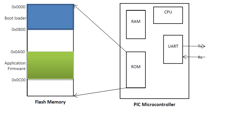
The processor will always start executing a code from a particular (start-up) memory location upon reset. Generally, microcontroller flashes the application code into start-up memory location when the bootloader is absent. In the presence of boot loader as shown in the figure "flash memory regions", the boot loader writes application code into any part of the memory location which user determines (ex: 0x0A00). In this demo, boot loader code will be flashed into microcontroller start-up memory location.
The job of the boot loader is to erase the application program memory and write received binaries into pre-determined program memory. The firmware has the reset vector pointer (0x0A00). Right after writing the binaries, the boot loader sets the program counter to reset vector pointer of the firmware to execute the code.
Before building application source code, one must specify the ROM range (after 0x0800h) which must be other than a start-up memory location. ROM range can be specified in the IDE project->properties->xc8linker->memory model->rom ranges
Boot Loader Source Code
The boot loader is basically the low level driver of PIC and is implemented in C. The source code of it is made freely available on the GitHub.
Algorithm
1. Configure IO port2. Configure UART baud rate with 115200 to communicate with the Android device.
3. Receive NVM address range request command from the host (Android device), in return PIC sends back NVM programmable program memory start and end address.
4. Receive START command
5. Send ready for FIRMWARE_HEADER command to the host.
6. Receive firmware header. Header consists of Application firmware size, and reset vector address.
7. Erase application program area and update flash base pointer with the reset vector address of the application.
8. Receive application binary chunks in packets each of NVM page size of the PIC microcontroller. Load the binaries into the program memory.
9. Jump to the reset vector location of the app to execute it.
Android application (Host)
Android device is the host which initiates the firmware update process. The host application has been written in Java and consists of user friendly GUI on font end through which user can interact with the app.
GUI
It consists of 3 buttons to select and connect one of the Bluetooth modules from the list, to select one of the hex files from the internal storage of the android device and to update the firmware. List Views displays available hex files and paired Bluetooth devices.

Software
Software is implemented in JAVA, again the source code of it is freely available on the GitHub.
Application firmware hex file must be converted to binary file before loading it into the PIC flash memory.
To convert hex to binary I defined couple of JAVA classes on the android platform. It basically takes hex file as an input and decodes it for the binary, for more information please have look at my another project IntelHexToBin Convertor. For the app, .hex file must be in the Intel format. MPLAB C compiler generates .hex in the Intel hex format.
The generated application firmware hex file is stored on the internal storage of the android device. Any number of hex files can be stored on the device. The GUI facilitates user to search the available hex files from the storage and select one of them to send it through Bluetooth communication link to PIC.
Algorithm
1. List paired Bluetooth modules and select one of them to establish communication link.2. Read selected hex file.
3. Decode hex file to get the binary data.
4. Divide the huge number of binary data into packets.
5. Send the START command to PIC.
6. Receive FIRMWARE_HEADER request from PIC.
7. Send firmware header. Header consists of Application firmware size, and reset vector address.
8. Receive Header acknowledgement.
9. Send application binary chunks in packets each of NVM page size of the PIC microcontroller.